GEOTECHNICAL ENGINEERING
CELBRIDGE
HomeGeophysicsElectrical resistivity / VES (Vertical Electrical Sounding)

Electrical Resistivity Surveys & Vertical Electrical Sounding in Celbridge

Practical geotechnics, field-tested.

LEARN MORE

A residential development near the Liffey hit unexpected soft lenses at 4 metres last spring. No borehole caught it, but the electrical resistivity survey we ran across the site flagged the anomaly in half a day. In Celbridge’s glacial till and alluvial corridors, drilling alone can miss transitions between gravel lenses and silty clays. Vertical Electrical Sounding gives us a continuous resistivity profile with depth, letting the design team see where bearing strata actually sit. For sites close to Castletown House or along the R403, we combine resistivity lines with test pit data to ground-truth the geophysics, then feed the model straight into foundation decisions.

Electrical resistivity profiling reveals what boreholes miss: continuous stratigraphy, perched water, and karst cavities hidden between drill points.
Our service areas

How we work

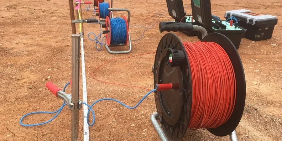
We deploy a multi-electrode system with 48 to 72 steel electrodes spaced between 2 and 5 metres, running a Wenner-Schlumberger array that captures both lateral and vertical resistivity variation. Current injection and potential measurement cycle automatically through the switchbox, building a 2D pseudosection in real time on a ruggedised field tablet. In Celbridge’s damp winter conditions, contact resistance can spike in gravelly topsoil, so we pre-wet electrodes with a saline solution and check ground coupling before each spread. Post-processing uses RES2DINV for smoothness-constrained inversion, producing depth sections calibrated to local borehole lithology. When we need deeper penetration—say 20 to 30 metres for a piled foundation study—we extend the array length and switch to a dipole-dipole configuration. The resulting cross-sections clearly resolve clay-gravel interfaces, water table depth, and potential dissolution features in the underlying limestone. For sites where seismic velocity is also required, we run parallel MASW profiles to derive Vs30 alongside the resistivity model.
Electrical Resistivity Surveys & Vertical Electrical Sounding in Celbridge
Technical reference — Celbridge

Site-specific factors

The geological contrast between Celbridge’s northern till plateau and the Liffey floodplain south of the village is stark. On the higher ground, lodgement till sits directly on Carboniferous limestone, and resistivity values above 200 ohm-m often indicate dry, compact material—generally good bearing. Down by the river, interbedded alluvial silts and peat lenses drop below 30 ohm-m, and that’s where differential settlement becomes a real concern. The bigger hidden risk is karst: dissolution channels and buried dolines in the limestone bedrock create abrupt resistivity lows surrounded by high-resistivity rock. A single borehole can miss a 3-metre-wide void by two metres. Our resistivity lines sample continuously along the profile, so these features show up as sharp lateral contrasts. On one Celbridge school extension, the survey picked up a suspected solution feature at 8 metres depth; follow-up probing confirmed a clay-filled cavity that would have compromised a pad footing. We also watch for anthropogenic noise—buried services, reinforced concrete foundations, and overhead power lines along the Dublin Road can couple into the array, so we notch-filter 50 Hz and record background levels before acquisition. For sites with significant karst potential, the resistivity data feeds directly into a targeted grouting programme to stabilise voids before construction starts.

Need a geotechnical assessment?

Reply within 24h.

Email: contact@geotechnical-engineering.co

Regulatory framework

ASTM D6431-18 (Standard Guide for Using the Direct Current Resistivity Method), Eurocode 7 – EN 1997-2:2007 (Ground investigation and testing), IS EN ISO 22475-1 (Geotechnical investigation – Sampling and groundwater measurement), IAEG Commission on Engineering Geological Mapping guidelines

Reference parameters

ParameterTypical value
Array configurationWenner-Schlumberger, dipole-dipole
Electrode spacing (typical)2–5 m (1 m for high-resolution)
Maximum investigation depthUp to 40 m (depending on array length)
Measurement cycles per spread400–1200 data points
Inversion softwareRES2DINV / EarthImager 2D
Line length per setup47–355 m (48–72 electrodes)
Typical survey duration (500 m line)4–8 hours field + 1 day processing

Frequently asked questions

How much does an electrical resistivity survey cost in Celbridge?

For a typical residential or small commercial site in Celbridge, budget between €540 and €1000 for a single-line 2D resistivity profile with interpretation report. The final figure depends on line length, electrode spacing, terrain access, and whether multiple parallel lines or 3D grids are required. We provide a fixed-price quote after reviewing site plans and the specific investigation objectives.

How deep can the resistivity method investigate on Celbridge sites?

Investigation depth is controlled by the total array length, not by the equipment power. With a 235-metre spread using 48 electrodes at 5-metre spacing, we typically resolve features down to 35–40 metres below ground surface. For shallower targets—say 8 to 15 metres for foundation studies—we tighten electrode spacing to 2 metres and shorten the line, which improves near-surface resolution.

Can you survey a site with existing buildings or buried utilities?

Yes, but with constraints. We adapt the electrode layout to available open ground, run lines along site perimeters, and use roll-along techniques to extend coverage. Buried metallic services (water mains, armoured cables) create conductive noise, so we map known utilities beforehand and offset lines where possible. Reinforced concrete slabs act as equipotential surfaces that mask deeper signals, so we avoid deploying electrodes directly on them.

Location and service area

We serve projects across Celbridge and surrounding areas.

View larger map